I had to spray some IPA on some of the wires so to reveal their colours and document their connections.
The main PCB was so grubby I couldn't discern some of the parts, let alone their values.
So the first thing I did was to spray it multiple times with 'Tuff Stuff,' and then wash it with warm water and a soft brush after each time.
Here the parts were finally revealed (see photo below). Aesthetically, the board is gorgeous to look at from the top. The backside is another story, though, as these boards were clearly soldered by hand from factory. The solder joints are inconsistent and tons of flux were left behind.
Somewhat automatically, because of force of habit, I immediately did a complete recap of the main board, as shown below. This was rather silly, though, since my modifications will render about half of the newly-installed capacitors redundant. Later on I did remove the more expensive ones from the board, for future use in other projects.
I also, of course, preserved this absolutely gorgeous Ducati-branded film capacitor!
Here's an overview of the clean and recapped main board:
I then turned my attention to the CRT driver board, shown below in its original (though slightly cleaned up) condition.
This board was a priority for the restoration, as a photo originally posted by the seller (reproduced below) showed very inconsistent horizontal scanning. This is usually caused by bad capacitors and/or diodes leaking reverse current in the driver circuit. Another thing this picture shows is a conspicuous absence of TV snow/static. This suggests a break in the tuner/IF chain, but that doesn't matter to me since I am converting it to baseband anyway, and the tuner will be disconnected.
I started by pulling all electrolytic capacitors and checking their health off-circuit. One of them was already visually compromised: the shrink-wrap around it had partly melted due to proximity to parts that operate quite hot. This has almost certainly dried the electrolyte within.
Checking the capacitor with an LCR meter, it first measured as a resistor, which betrays the presence of cracks in the oxide layer. In a healthy capacitor, the oxide works as a dielectric and prevents the flow of DC. However, when it cracks, the capacitor allows DC through and behaves (partly) as a resistor.
Upon a second measurement, the capacitor did show up as a capacitor, but a ~27pF one (the nominal value was 10µF). In other words, this part was hardly a capacitor anymore: the dry electrolyte doesn't allow the ions to flow and the fields to form, so the capacitance disappears. Several other capacitors on the board had suffered a similar fate, which goes a long way in explaining the distortions in the horizontal scan.


A different example is shown in the photos below: this blue, high-voltage capacitor had a nominal value of 8µF. It measured instead as a 10µF cap. Contrary to what many hobbyists seem to believe, capacitance does not increase miraculously or spontaneously in any capacitor, no matter how old. What is happening here is a measurement artifact: the LCR meter or multimeter infers the capacitance based on how long it takes to charge the capacitor. But if the capacitor, unlike the example above, still has fluid electrolyte and is leaking DC because of cracks in the oxide layer, it will take longer to charge. The meter then incorrectly interprets it as higher capacitance. To prove this, I connected the capacitor to a multimeter in resistance mode. Unsurprisingly, the multimeter saw the capacitor as a ~40MΩ resistor.
Now this is the tricky thing about old capacitors: they tend to have both minor cracks in the oxide layer (which show up as a seeming increase in capacitance) and partly dried electrolyte (which shows up as a reduction in capacitance). When these different effects balance out, you may get capacitance readings well within tolerance and conclude that the capacitor is still good. Do yourself a favour: replace old capacitors even if they seem to check out (exception: very large capacitors with screw-on or snap-in terminals tend to be truly robust), for these are consumable parts. Even if they actually are still good, soon they will not be.


Having fully recapped the CRT driver board, I turned my attention to its diodes. Even when diodes test okay in a quick multimeter junction test, they may still be (and often are) bad: the multimeter applies only a very small reverse bias voltage to check the junction. At the higher reverse voltages encountered during normal operation, a diode that checks out with a multimeter may actually be leaking significant reverse current. And since I already knew that the CRT driver board had issues, I preemptively replaced almost all (details below) diodes in it.
Interestingly, though, and as illustrated below, many of the original diodes had their leads folded into little circles. This is not to create an inductor, as doing so would simply increase the inductive reactance of the diode and compromise its operating frequency. The reason the Italians did this was heat dissipation through the leads: they essentially created little radiators by keeping the leads long and folded upon themselves.
I, of course, also folded the leads of the new diodes in the same way, and for the same reason. To avoid inadvertently creating induction, I made sure the folded leads physically touched the short, horizontal stub close to the diode's body, effectively short-circuiting any potential inductance.
At first, I also replaced a large diode right next to the flyback transformer (shown below) with a higher-rated modern equivalent. But shortly thereafter I changed my mind and put the original one back: the Italians deliberately used a package meant for panel mounting in a diode assembled on a PCB. The only reason for them to have done that is the (much) higher heat dissipation capacity of the large metal package. Therefore, having carefully tested the original diode off-circuit and finding it to be in perfect condition, I returned it to the PCB.

The photo below shows an overview of the CRT driver board after restoration. I kept the original power transistors because (a) they are still working fine, and (b) they are germanium transistors for which there are no modern drop-in replacements. Yes, there are higher-rated silicon transistors that could, in principle, replace them, but the bias would probably need to be different. Re-biasing these transistors can be done, especially with all the calibration points these boards have, but that is something I will do when I need to do it; not yet.

The next sub-system to get my attention was the power supply unit (PSU) board shown below. I must confess that, when it comes to PSUs, my default choice is to simply replace them. Vintage PSUs, such as this one, are often not reliable. It would be unfortunate to spend all the time and effort required to lovingly restore a vintage system such as this radio/TV combo, just to watch it go up in smoke because of a failing PSU a few weeks in. Replacing vintage PSUs with reliable modern equivalents is a responsible conservation measure, not a defacement of the original system.

For the replacement, I used an off-the-shelf Mean Well 12V PSU that I then calibrated down to 10.8V, the nominal voltage for this system. I affixed the new PSU to the aluminum bar that held the original PSU board, and it fit perfectly. Notice that I also added an extra little board with a DC-decoupling filter (inductor plus capacitor) that was present in the original (though not in the schematics), and without which I think the CRT driver board wouldn't oscillate. I, of course, used a brand-new capacitor rated for 125C here. But I did re-use the original inductor, as inductors usually have higher reliability and more longevity.

Only after having installed the new PSU did I notice that I had forgotten an important detail: this system expects the common ground to be connected to the chassis/earth ground that provides the voltage reference for just about everything. So I added a new connection for that purpose. Remember that connecting common ground to earth ground, although often a good idea, must be done only once in the circuit, so to prevent the formation of nasty ground loops. As shown in the photo below, I made the connection immediately after the DC power supply.
At this point, having dealt with the problematic CRT driver board, replaced the PSU with a reliable modern equivalent, and cleaned/recapped the main board, I was finally in the position to think about how to modify this system so to make a composite monitor out of it. The schematics are shown below. I found this diagram to be mostly, yet not completely, correct for my specific unit. In any case, it is good enough to identify main sub-circuits.
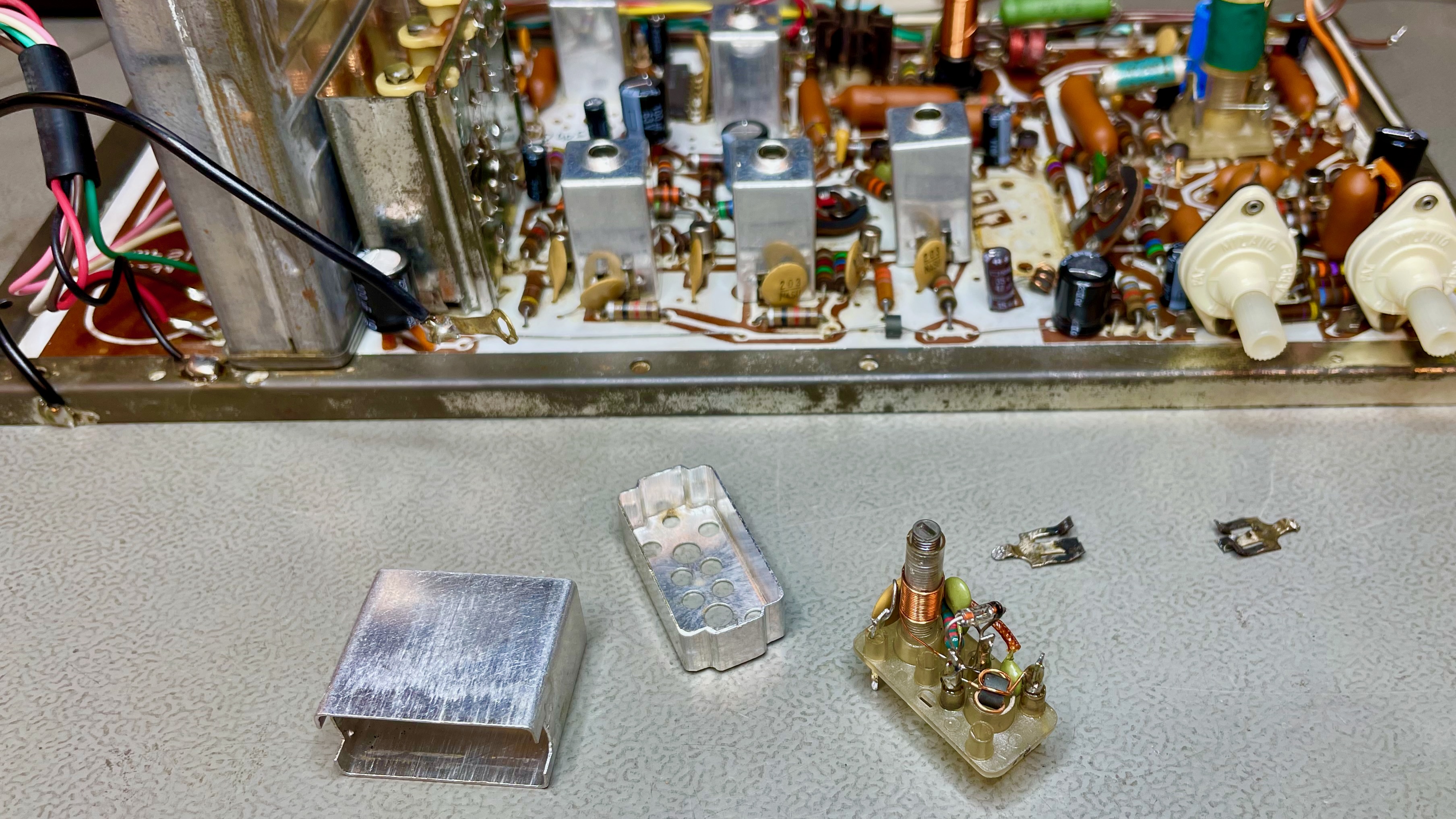
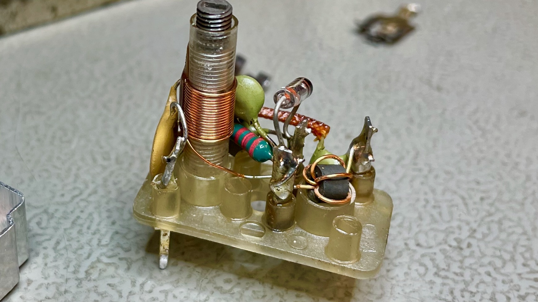
The key now was to sever the connection between the tuner/detector/IF and the beginning of the amplification chain. Based on the schematics above, the connection is done through diode OA90, between a BF173 and a BC108 transistor (that BC108 is the first stage in the amplification chain). Therefore, I had to remove that diode. At first, however, I couldn't find it on the board, until I realised that it was almost certainly hidden in one of the cans. I pulled what I thought was the relevant can and opened it up.
Sure enough, there was the OA90 diode lurking inside the can. To sever the connection in a clean and comprehensive manner, I decided to remove the entire can plus two nearby inductors (marked as the lower VK200/10 and the NCV1T in the schematics). This way, the base of the BC108 transistor was now un-driven and ready to receive the composite signal.
The edited schematics below show what I intended to do: terminate the composite signal with a 75Ω resistor to chassis ground (this is the impedance the SOL-20 expects to see), and then feed it through a 4.7µF non-polar capacitor (to eliminate DC) into the base of the BC108. Unfortunately to me, at this point I incurred in two oversights, one of which was to forget to add the 75Ω termination resistor.
Still unaware of what I had overlooked, I pulled the BC108 to test it off-circuit, before relying on it for the rest of the (hopefully long) life of the newly-born composite monitor. Good that I did so, because the transistor had a gain of only x9, when something more like x300 would be expected.
I replaced the transistor with the same part (somehow BC108s are still made today!).
Having then performed the modification, I was disappointed to be greeted with a washed-out, over-saturated image on the monitor. I was using an Apple ][+ to drive the video.
To understand the problem, I hooked up my oscilloscope to the base of the (now new) BC108, the very point where the composite signal was being injected. I accidentally bumped the probe setting to x1, while the oscilloscope expected x10, so all readings are in fact 1/10th of what the oscilloscope showed. Nonetheless, the issue became immediately clear: although the AC amplitude of the signal (~1.3V peak-to-peak) was okay, there was a DC component of 5.12V! This biased the transistor at the top of its operating range, leading to the over-saturation. The ideal bias should put the DC component in the middle of the transistor's operating range, which is about 2.2V.

Here is where my second oversight was revealed: when I disconnected the IF from the amplifier chain, I also cut the balancing mechanism of the bias network through the voltage divider R28/R29 and the now-removed R27. Because of this, the base of the BC108, which is pulled up to the 10.8V power rail by resistor R34 (47KΩ), ended up drifting upwards to about half of the power rail level.
To anchor the DC bias at a predictable and solid level, I had to add a pull-down resistor connected to the base of the BC108, so to form a voltage divider with R34 and thereby feed the base with a stable VDC level. Running the numbers, I calculated that a 12KΩ resistor to ground should give a DC bias of precisely 2.2V, the sweet spot. See the updated diagram below.
I also remembered to add the 75Ω termination resistor the SOL-20 expects to see when connected to this monitor-to-be. I did so right at the input socket, so it is the very first thing the signal sees.
Here's what the modified circuit looks like on the PCB. By removing some of the now-redundant components, I freed some very convenient pads to connect everything neatly, as if from factory. Notice that I also replaced R34 with a brand-new 47KΩ resistor, as the original's value had drifted down quite a bit.
I used the remaining cans and a few cable ties to manage the shielded cable running from the RCA socket to the PCB itself. It is important to physically secure this cable firmly, so to avoid strain on the solder joints.
And since I was already at it, I replaced some components of the black-level clamp, including transistor BC178 (now a BC557B), diode BA145 (now a 1N4148) and capacitor C55 (now a 2.2µF tantalum), for longevity and reliability. This clamp will have little visible impact on the video after the baseband conversion, but hey, why not?
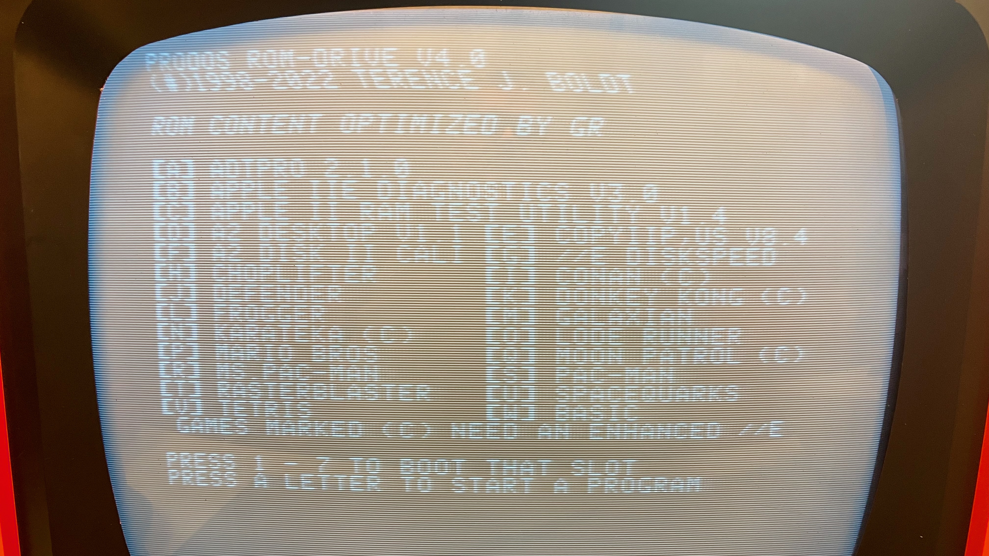
Finally, I was greeted with a clear, stable, high-contrast image (the photo doesn't do justice to the real thing):
Even graphics display well (below, the graphics are being generated by an Apple ][+ that I happened to have at hand for testing). There are some minor distortions in the geometry that become visible when the screen is filled with graphics, but with the SOL-20 none of this will be visible, as it has no full-screen graphics capability.
However, when I started playing some games, I realised that I had to turn the contrast knob all the way up to get a sharp image. With the contrast knob at around half-way, I got a milky image, such as shown below. This is not right...
To understand the problem, I hooked up my oscilloscope again, to the same pad. The result is shown below. Notice that the DC bias level is now spot on: 2.2V, just as calculated and designed for. However, the amplitude of the AC signal is now just over 0.8V peak-to-peak, when before it was ~1.3V. Why did this happen?
The problem here is that I was using an Apple ][+ for testing, and the potentiometer that regulates the amplitude of the composite signal coming out of the computer was dampening it too much. I didn't see this effect before because I had forgotten to add the 75Ω termination resistor, and the computer was thus driving a relatively high input impedance. But with the termination resistor in place, the signal required less dampening for proper contrast. Therefore, there is in fact no problem with the newly-born monitor: the circuit is doing exactly what it is meant to do.
Here are some glamour shots of the now repaired, restored, and modified system:


This has been Part I of a two-part series. Two major steps remain to be taken: the restoration of the enclosure (which will be re-sprayed with a new color, so to match that of the SOL-20) and the design and incorporation of a little AM receiver. Although this set incorporated both radio and TV receivers from factory, the two were never meant to operate at the same time (who would want to watch a TV show while listening to the radio?). Therefore, the Italian engineers did what any competent engineer would have done: re-use circuitry between radio and TV. The BC108 amplifying stage discussed above, for instance, is shared by both modes. For this reason, I need to add a bespoke little radio receiver somewhere within the enclosure, which will use both the existing volume and tuning knobs already present. From the user's perspective, thus, all will look and feel entirely original. In fact, you may have noticed, in the photos above, that I already removed a number of large components of the tuners to make space for a daughter card, off to the right.
Stay tuned for the next steps!